Netgen 6.2 adds the possibility of defining Integrals on codimension 2 objects (on the boundaries of boundaries - BBND). This enables i.e. the definition of currents on a segment in a 3D geometry, to compute the magnetic field of a thin wire. Because of the way Netgen creates it's mesh at the time, only boundary curves of surfaces can be defined as BBND for now. They can be defined using the class SplineSurface . Its constructor takes a CSG object as argument. Then you have to cut this object with line segments. The following function defines a square with BBND condition "contact" on the top and "wire" else.
def CreateSquare():
    base = Plane(Pnt(0,0,0),Vec(0,0,1))
    surface = SplineSurface(base)
    pts = [(-0.5,-0.5,0),(-0.5,0.5,0),(0.5,0.5,0),(0.5,-0.5,0)]
    geopts = [surface.AddPoint(*p) for p in pts]
    for p1,p2,bc in [(0,1,"wire"), (1, 2,"contact"),(2,3,"wire"),(3,0,"wire")]:
        surface.AddSegment(geopts[p1],geopts[p2],bc)
    return surface
The base of our SplineSurface is a Plane with Normal vector pointing in positive z-direction. Next we define the start and end points of the splines. We add these points to the SplineSurface and save the return values (this are the internal point numbers on the surface). Then we add our splines with the respective BBND name to our geometry object. The base plane is then cut with planes with normal vector being the cross product of the base plane and the spline vector. Therefore it is important that we define the splines in the right order, when the normal vector of the plane is facing us we have to define them clockwise (I'll fix that in the future). Next we create a CSGeometry object, add the surrounding Sphere, our SplineSurface and create a Mesh.
geo = CSGeometry()
geo.Add(Sphere(Pnt(0,0,0),1).bc("outer").mat("air"))
geo.AddSplineSurface(CreateSquare())
mesh = Mesh(geo.GenerateMesh(maxh=0.2))
Draw(mesh)
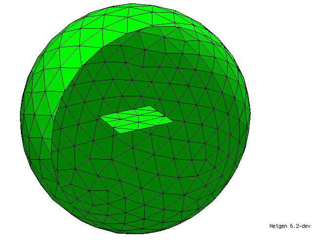
This generates the following mesh:

In article Using BBND to compute the magnetic field of a thin wire, we want to use this geometry:

We create this geometry by cutting a Cylinder with splines in the same way. The start and end points of the splines have to be computed (they are then projected onto the cylinder, so a "good enough" approach is fine) and then the cylinder is cut with planes with normal vector being the cross product of the normal vector of the cylinder in the start point of the spline and the spline vector (again direction of definition is important!). The intersection of this cut is then defined as a BBND condition with the prescribed name. The file to create this geometry is attached as createCoil.py. We define a small part of the longer side of each coil part with the BBND condition "contact" , and the rest as "wire". This will enable us to impose a prescribed current on the contact.
If you have any questions or comment feel free to leave them below :)

